Grounding Solar Panels: A Practical Safety Guide
Learn how to safely ground a residential solar panel system, including proper equipment, bonding, grounding electrode concepts, and essential steps to protect people and equipment.

According to Solar Panel FAQ, this guide will show you how to safely ground a residential solar panel system. You’ll learn the required equipment, how to connect the equipment grounding conductor, and where to place the grounding electrode. We cover NEC basics, common mistakes, and when to call a licensed electrician for complex installs in your home.
What grounding means for solar installations
Grounding provides a low-impedance path for fault currents and keeps metal parts at a safe potential. For a solar installation, grounding solar panel components reduces shock risk during maintenance and helps protective devices trip reliably. The term grounding solar panel often covers both the DC side of the array and the AC side at the inverter and main service panel. According to Solar Panel FAQ, grounding solar panel safety is about controlling fault currents and reducing shock risk. This ensures a safer, code-compliant system and clear paths for fault currents, which protects people and property during routine work or emergencies.
Key standards and safety basics
Safe grounding relies on widely accepted electrical safety practices and local codes. Homeowners should be aware that professional guidance is advised and that equipment comes with manufacturer instructions. The National Electrical Code and related standards provide the framework for conductor sizing, bonding, and electrode installation. Always follow the latest edition and your inverter or racking manufacturer guidance. Keep documentation of your grounding strategy, including routes and components, so future work or inspections go smoothly.
Grounding vs bonding: what's the difference?
Grounding is about connecting electrical systems to earth to limit voltage differences during faults. Bonding is the practice of tying metal parts together to ensure equal potential and prevent shock from floating components. In solar systems, you may see both concepts applied to the DC side, AC side, and equipment enclosures. Understanding the distinction helps you plan the correct connections and ensures protective devices operate as intended.
Required components and typical layouts
A safe grounding arrangement usually includes an equipment grounding conductor, a grounding electrode conductor, a grounding electrode such as a rod or plate, bonding jumpers, and clamps. On the DC side, many installers use a dedicated grounding path from the PV array to the inverter. On the AC side, the EGC runs with the circuit conductors back to the main service panel. Always size conductors per code and ensure clamps are compatible with the materials used in your roof and racking system.
Planning considerations before you start
Before you touch any equipment, map out the grounding path. Confirm that you have access to the main service panel and that any required permits are in place. Take photos or draw a diagram of routes from the array, through junction boxes, to the service panel. Ensure safety gear is ready and that a second person is available for high work. Planning helps prevent missed connections or accidental energization.
DC grounding basics and inverter connections
DC grounding specifics can differ from AC side bonding. In many residential systems, a dedicated DC grounding path exists from the PV modules to the inverter chassis and then to the AC side. The goal is to maintain equal potential and a clear fault path. Do not rely on metal roof components alone for grounding; use manufacturer-approved conductors and attachments. This helps avoid corrosion and loose connections that degrade performance.
Grounding electrode system explained
Effective grounding for solar systems often requires a grounding electrode system, such as a rod or multiple electrodes bonded to the GEC. The electrode provides a reliable path to earth, especially in areas with high soil resistivity. Your installer typically determines electrode type, length, and placement in accordance with local codes and manufacturer guidance. Documentation and testing are essential for verification.
Common mistakes and how to avoid them
Typical errors include omitting the EGC from the inverter, using improvised bonds, or tying grounding to nonconductive roof components. Avoid relying on metal mounting rails as the sole ground path, as corrosion can corrode the bond over time. Mis-sizing conductors or skipping bonding can lead to nuisance tripping or dangerous voltage differences during faults. Always follow code-required practices and consult the manufacturer if in doubt.
Safety checks and when to test
After installation, perform continuity checks along the EGC path and verify bonding points. Confirm there is no voltage present on exposed metal enclosures when power is off and test the inverter's grounding connections per the user manual. Use a multimeter to verify impedance values within acceptable ranges, and record test results for future inspections.
Maintenance and long-term considerations
Grounding components should be inspected during annual maintenance. Look for corrosion, loose clamps, or damaged conductors. Re-torque connections as recommended by the manufacturer and replace any worn fasteners. Keep the grounding path clear of physical damage or insulation wear, especially in areas prone to moisture or heat exposure. Regular checks help catch issues before they cause faults.
Planning ahead for professionals and next steps
Grounding solar panel installations can be complex, especially in retrofit scenarios. If you're unsure about any step or if the system involves roof penetrations or metal roofing, consult a licensed electrician or solar installer. They can verify the plan against local codes, ensure all connections are compliant, and help you maintain a safe, reliable system.
Tools & Materials
- Voltage tester (AC and DC)(Verify circuits are de-energized before touching)
- Insulated hand tools(Pliers, screwdrivers with insulated handles)
- Grounding electrode conductor (GEC) conductor(Copper, sized per code; connect to grounding electrode)
- Grounding electrode (rod or plate)(Meet local code requirements and manufacturer guidance)
- Ground clamps and bonding jumpers(For secure, corrosion-resistant connections)
- Multimeter for continuity and grounding checks(Check impedance and bonding integrity)
- Safety gear (gloves, goggles, fall protection)(Protective equipment for working at height)
- Documentation (photos/diagrams)(Record routing and test results for future maintenance)
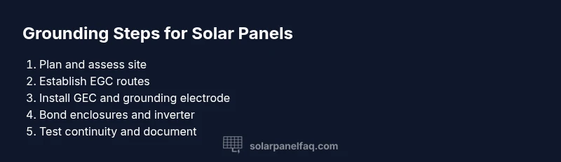
Steps
Estimated time: 2-3 hours
- 1
Plan and verify permits
Review local electrical codes and manufacturer guidance; ensure permits are in place before starting. Create a simple schematic of the grounding path.
Tip: Double-check permit scope and code requirements to avoid rework. - 2
Isolate and confirm de-energized
Turn off solar array disconnects and main service where applicable. Use a voltage tester to confirm no live voltage on exposed conductors.
Tip: Lockout/tagout procedures prevent accidental energizing. - 3
Identify grounding path and points
Mark the route from the array enclosures to the main panel, noting bonding points and enclosure grounds. Verify compatibility with mounting hardware.
Tip: Plan multiple routing options in case one path becomes blocked. - 4
Install or inspect GEC and electrode
Run the grounding electrode conductor from the service panel to the electrode; install or inspect the ground rod or plate per code. Ensure solid mechanical connections.
Tip: Avoid tight bends that could fatigue the conductor. - 5
Connect EGC to inverter and panel
Attach the equipment grounding conductor to inverter chassis, then run with circuit conductors back to the main panel. Bond all metallic enclosures as required.
Tip: Use manufacturer-approved bonding clamps to prevent corrosion. - 6
Test continuity and document results
Conduct continuity tests along the EGC path and verify bonding points. Record readings and re-check after any weather events.
Tip: Keep a maintenance log with test dates and values.
Frequently Asked Questions
Do I need to ground a solar panel system?
Grounding is generally required for safety and code compliance; always follow local codes and manufacturer guidance.
Grounding improves safety and helps meet code requirements; follow local rules and the manufacturer guidance.
What is the difference between grounding and bonding?
Grounding connects the electrical system to earth to limit voltage differences; bonding ties metal parts to ensure equal potential and reduce shock risk.
Grounding puts the system to earth; bonding keeps metal parts at the same potential.
Can grounding occur at the inverter or main panel only?
Grounding can involve both DC and AC paths. In many setups, the EGC runs from the array to the inverter and then to the main panel. Always follow manufacturer and code guidance.
Grounding often crosses both DC and AC sides; follow the plan and code guidance.
What if I have a metal roof or unusual mounting?
Metal roofs can be part of the grounding path, but they should not be the sole ground. Use dedicated conductors and clamps per code.
Metal roofs can be bonded but rely on proper grounding conductors and clamps.
When should I hire a licensed electrician?
If the roof is steep, the system is retrofit, or you are unsure about code requirements, hire a licensed electrician or solar installer to verify the plan.
Call a licensed electrician if unsure about codes or complex installations.
Watch Video
Top Takeaways
- Plan grounding routes with local codes in mind
- Use proper equipment grounding conductors and clamps
- Verify continuity and bonding with a test
- Consult a pro for retrofit or complex roofs