Solar Panel Testing Procedure PDF: A Practical How-To
Learn how to perform a comprehensive solar panel testing procedure pdf with safe, repeatable tests, essential tools, and a printable reporting template. This guide from Solar Panel FAQ helps homeowners and buyers assess panel health accurately.

This guide explains how to perform a solar panel testing procedure pdf workflow at home or with a contractor. You’ll learn the essential tests, required tools, and safe steps to evaluate voltage, current, insulation resistance, and shunt faults. According to Solar Panel FAQ, follow a structured, safety-first approach and compare readings to manufacturer specs.
What is a solar panel testing procedure pdf and why it matters
A solar panel testing procedure pdf is a structured document that outlines the tests, data sheets, safety notes, and acceptance criteria used to evaluate photovoltaic installations. For homeowners and installers, having a formal PDF template makes repeat testing consistent, traceable, and easy to share with electricians, inspectors, or lenders. According to Solar Panel FAQ, a clear, standardized protocol helps ensure you measure the same parameters under the same conditions every time, reducing guesswork and enabling safer, more reliable operation. The core goal is to verify that each panel and string behaves as designed under real operating conditions, and to document any deviation for timely corrective action.
Core tests included in the PDF
A robust testing procedure pdf lists the essential electrical checks you should perform on solar panels and strings. Typical tests include an I-V curve to capture current vs voltage behavior under daylight, open-circuit voltage (Voc) and short-circuit current (Isc), and continuity checks across series strings. Insulation resistance tests assess leakage between conductors and the mounting frame or ground, while diode checks on module bypass diodes help identify failed paths. When feasible, thermal imaging notes can flag hot spots that correlate with degraded cells. Each test is paired with expected ranges from the manufacturer datasheet or system design, plus a dedicated data field to record the reading, time, and test conditions.
Safety and prerequisites before testing
Testing involves potential high voltages and rooftop access. Before you begin, review the site safety plan, wear PPE (gloves, goggles, and non-slip footwear), and ensure a stable ladder or platform. If you must isolate the array, follow proper lockout-tagout practices and confirm the system is de-energized before connecting test equipment. Schedule tests for daylight hours when irradiance is stable, and avoid wet surfaces, dew, or windy conditions that can cause slips or misreadings. Document any safety incidents and have a plan to halt work if weather deteriorates.
Tools and materials checklist
Before starting, gather essential tools and materials. This list prioritizes safety and data integrity:
- DC multimeter with appropriate voltage/current ranges (required)
- DC clamp meter and insulation tester (required)
- Insulation resistance tester (megohmmeter) (required)
- I-V tester or data logger compatible with solar arrays (required)
- Test cables, clamps, and properly rated connectors (required)
- Personal protective equipment: gloves, safety glasses, non-slip shoes (required)
- Safety harness and roof anchors for elevated work (required if on a roof)
- Manufacturer datasheets and wiring diagrams (recommended)
- A portable work surface or bench with non-conductive padding (optional)
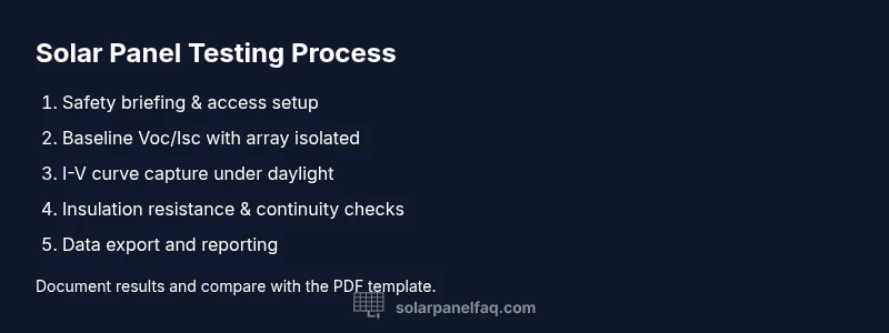
Step-by-step workflow overview
The pdf should present a logical, repeatable flow that minimizes backtracking. Start with a safety briefing and baseline measurements, then proceed to DC measurements (Voc/Isc), followed by load testing (I-V curve) and finally insulation and continuity checks. End with data compilation, a succinct interpretation, and a printable report section. This structure keeps testing organized and audit-friendly.
How to structure the I-V test and data collection
To obtain a meaningful I-V curve, perform measurements under consistent daylight and document irradiance if possible. Record Voc and Isc first with the array isolated, then re-measure under load to capture the curve. Use a data logger or I-V tester to capture multiple points along the curve and export them to a CSV or PDF form for archival. Include notes on temperature, shading, and panel orientation, since these factors affect readings.
Interpreting results and reporting in the pdf
Interpretation focuses on identifying deviations from expected behavior, such as a broken bypass diode, a degraded cell, or a loose connection. If a test shows out-of-range values, flag the panel or string for repair or replacement, and document recommended actions in the report. The final PDF should include a summary page, test-by-test results, interpretation notes, and a section for follow-up tests. Keeping the report consistent across maintenance visits improves long-term performance tracking.
Additional resources and templates
Templates often include a cover page, test log pages, data tables, and a conclusion section. When possible, attach manufacturer datasheets and site photos for context. For ongoing projects, maintain a folder of PDFs per installation so future owners or technicians can review test history at a glance.
Tools & Materials
- DC multimeter (voltage/current)(Range suitable for panel voltage and current; read DC only)
- DC clamp meter / insulation tester(Clamp for Isc measurements; insulation tester for leakage checks)
- Insulation resistance tester (megohmmeter)(Test between conductors/ground and frame)
- I-V tester or data logger(Captures the I-V curve under daylight)
- Test cables, clamps, connectors(Use properly rated, clean connectors)
- PPE: gloves, goggles, non-slip shoes(Safety first during all tests)
- Roof safety gear (harness, anchors)(Required if testing on a roof)
- Manufacturer datasheets & wiring diagrams(Reference values and wiring layouts)
- Portable work surface(Non-conductive pad for non-panel surfaces)
Steps
Estimated time: 45-90 minutes
- 1
Assess safety and set up
Review the safety plan, wear PPE, and confirm access. Ensure tools are within reach and the area is clear of obstructions. This upfront step reduces risk during testing.
Tip: Double-check weather and ensure the array is de-energized before touching any conductors. - 2
Record baseline Voc/Isc with array isolated
Connect measuring devices to each panel or string, and record Voc and Isc. Use the lowest-risk path to access conductors and avoid shadowing panels during measurements.
Tip: Label each reading with string ID and time for traceability. - 3
Capture the I-V curve under daylight
Engage the I-V tester or data logger to collect multiple points along the curve. Note irradiance, temperature, and any shading effects that could skew results.
Tip: Take at least 3 spectrum points if possible to improve accuracy. - 4
Perform insulation and continuity checks
Test insulation resistance between conductors and frame/ground. Check continuity along strings and at junction boxes to detect loose connections or corrosion.
Tip: If readings spike or drop unexpectedly, pause and recheck connections. - 5
Correlate results with datasheets
Compare measured values to manufacturer specs and system design documents. Look for consistent deviations across a string that might indicate panel damage.
Tip: Document any outliers and plan targeted follow-up tests. - 6
Compile data and produce the pdf report
Export data to CSV, attach photos, and populate the PDF template with results. Ensure clear summaries and actionable recommendations.
Tip: Use consistent terminology and naming conventions across all reports.
Frequently Asked Questions
What is in a typical solar panel testing procedure pdf?
A typical pdf outlines safety steps, core electrical tests (Voc, Isc, I-V curve, insulation), data collection fields, and reporting templates. It also includes notes on test conditions and acceptance criteria.
A typical pdf includes safety steps, core electrical tests, and a reporting template. It helps keep tests consistent.
Do I need professional help to run these tests?
For rooftop systems or high-voltage configurations, hiring a licensed electrician or solar technician is recommended. They bring safety expertise and proper PPE for elevated work.
For rooftop or high-voltage systems, a professional is advised.
Can I use a home meter to perform solar panel tests?
A basic DC multimeter can measure voltage and current, but use appropriate ranges and follow safety protocols. For insulation tests, specialized equipment is typically required.
You can use a home meter for basic voltage checks, but insulation tests usually need proper gear.
What safety precautions are essential?
Wear PPE, secure ladders, de-energize the system when required, and avoid testing in wet conditions or on a windy roof. Have an emergency plan ready.
Wear PPE and ensure the system is de-energized when needed. Be prepared for emergencies.
Where can I download a free pdf template?
Check manufacturer guides, utility program resources, or Solar Panel FAQ resource pages for templates. Ensure the template is updated and matches your system configuration.
Look for templates on Solar Panel FAQ resources or official manufacturer guides.
Watch Video
Top Takeaways
- Prepare safety gear and plan testing windows
- Use the PDF template for consistent data collection
- Compare readings to datasheets and system design
- Document anomalies for follow-up actions
- Create a reusable testing workflow for future tests